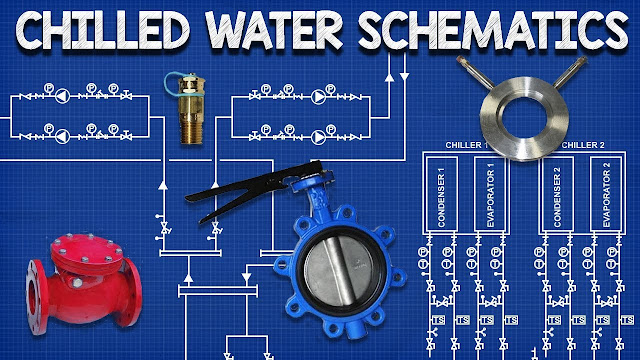
on video Chilled Water Schematics - How to read hvac engineering drawing diagram
We have individuals from Various Areas Requesting “Maps” when they mean Floor Plans and “H”- “Vac” Coverage Diagrams when they should be asking for H.V.A.C. Zoning Plans, But Real Confusion is occurring with the Actual Definition of Hvac Control Diagram, Hvac Airflow Diagram, Hvac P & Id and Hvac D & Id.
The question of what constituted or what is the different Between an Hvac Control Diagram, Hvac Airflow Diagram, Hvac P & Id and D & Id Has BEEN BRAGHT Up on Several Occasions and the Terms Although Similar Have distinctly different use.
The attached document may be a handy reference if someone outside of the technical field requires you to define or point out the different Between “hvac p & id”, “D & ID”, “Air Flow Diagram” or “Control Diagram”, it also represents to bring resolution to this nuisance contradiction in terminology.
For those with backgrounds in the Piping Field, where detailed P & Id’s Are the Standard, It Seems Strange That P & Id’s Are not Generated for Hvac Systems to the Detailed Level that they are for piping system. The question of what constituted an hvac control diagram, hvac airflow diagram and an hvac p & id has been bolt up on several occasions. This document is an attempt to ANSWER the question of why detailed p & id’s are not generally produced for the hvac discipline.
Simply Put, The Term P & ID is an acronym for piping and diagnostal instrumentation (The P Does not stand for process, process is show on pfd’s or process flow diagrams).
Control Drawings (Produced by an Ae Firm or General Engineering Office), also Termed Air and Water Schematics, which are very similar to P & Id's Are Produced for Various Projects by Multi-Disciplinary Design Offices, (These Drawings Often Indicate Viz. Sensors, Dampers, Simple Motor Controls etc.) Show General Rental of Components and Are Produced to correspond to the System Sequence of Operation Document and Are More Likely to Be Used by the Estimators and Controls Manufacturer to Produce A Points List / Controls Count Than A Construction Document (The System Sequence of Operation Document Indicates The Engineers Intent and Superses The Control Drawing IF The Two Documents Are in Conflict).


No comments